Skip to content

Mixed Reality

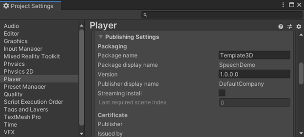
Decomposing the Unity UI Automatic Layout System including Vertical, Horizontal, and Grid Layout Groups

If you’ve ever tried to get the automatic layout system to work and it just didn’t, you’re not alone. What should have been a simple exercises in dropping three Text Mesh Pro components into a Canvas with a Vertical Layout Group caused me to end up spelunking through the layout system to find what it was trying to do, how it was doing it, and finding a way to resolve the problems. This is the journal of my journey – with a bit of reorganizing to make it more straightforward.

RectTransform and ILayoutElement

Unlike a Transform, which locates a GameObject in 3D space without a size, the RectTransform includes an inherent size in 2D space – there’s a width and height. If you’re trying to lay out items vertically, you should just be able to look at the height of RectTransform, add some spacing, and stack them. However, not so fast: the size of an element isn’t fixed. Some elements can shrink if necessary and some can grow if there’s more space available.

In Unity, an element has a minimum size, a preferred (ideal) size, and a flexible (maximum) size. However, you can’t infer all of this from RectTransform, so it needs a component that implements ILayoutElement. (See Object Hierarchy and Scripts in Unity for more on how GameObjects in Unity are comprised of components if this isn’t clear.)

ILayoutElement specifies the six float properties that you’d expect, with three values across two dimensions (minWidth, preferredWidth, flexibleWidth, minHeight, preferredHeight, and flexibleHeight). In addition, it specifies a layoutPriority integer and two methods (CalculateLayoutInputHorizontal and CalculateLayoutInputVertical). The layoutPriority allows multiple components that implement ILayoutElement to be attached to a single game object, and the component with the highest layoutPriority value will control the settings. An ILayoutElement conveys that it doesn’t want to specify a value by setting the value to -1.0f. This allows some flexibility for different ILayoutElements to set different end values.

The two methods (CalculateLayoutInputHorizontal and CalculateLayoutInputVertical) are methods that a consumer of the interface is supposed to call prior to using the horizontal or vertical variables (respectively). This gives the component implementing ILayoutElement a chance to make sure that the values are up to date.

ILayoutController and ILayoutGroup

If you have a set of objects with the appropriate size values from ILayoutElement, it should be possible to arrange them on a 2D canvas. That’s what the ILayoutController interface does. It contains two methods (SetLayoutHorizontal and SetLayoutVertical) that a consumer can call to cause the layout controller to arrange its children on the canvas. There’s a different interface, ILayoutGroup, that the out-of-the-box layout components implement – but ILayoutGroup is a direct descendant of ILayoutController, and it doesn’t specify any additional properties, fields, or methods. In short, they’re functionally equivalent. It’s probably best to implement the ILayoutGroup interface, because that’s the interface most components expect to find.

This leaves the question about how these interfaces are used and how they’re called.

VerticalLayoutGroup, HorizontalLayoutGroup, HorizontalOrVerticalLayoutGroup, and LayoutGroup

The implementation of ILayoutGroup is, as might be expected, LayoutGroup – however, it’s an abstract class. In other words, you can’t use it directly, but it’s supposed to contain some base implementations that are helpful to its children. What’s interesting about LayoutGroup is the objects it derives from and the additional interface it supports.

Most scripts in Unity derive from MonoBehavior. This provides the baseline functionality that scripts need. However, LayoutGroup derives from UIBehaviour. This is a subclass of MonoBehavior and importantly adds additional events: OnCanvasGroupChanged(), OnCanvasHierarchyChanged(), OnDidApplyAnimationProperties(), and OnRectTransformDimensionsChange(). These events, plus the OnTransformChildrenChanged() method from MonoBehavior, are signals to try to lay out the children again, because there’s been a change that may be important.

As an aside, LayoutChange doesn’t implement OnCanvasHierarchyChanged() or OnCanvasGroupChanged() for some unknown reason, though it seems as if those events should trigger the layout to be recalculated.

The layouts that we use directly, Vertical Layout Group and Horizontal Layout Group, don’t derive from LayoutGroup directly – though Grid Layout Group does. Instead, Vertical Layout Group and Horizontal Layout Group derive from a class, HorizontalOrVerticalLayoutGroup, which in turn derives from LayoutGroup. This is a good use of reusability, as the only real difference between vertical and horizontal grouping is the axis. As a result, HorizontalOrVerticalLayoutGroup can do the heavy lifting, with both Vertical and Horizontal Layout Groups being a thin shim above it to provide specific user interface and parameters.

The Other Classes: ILayoutSelfController and ILayoutIgnorer

All of the interfaces for layout are in the same ILayoutElement – so you won’t find files for the interfaces like ILayoutGroup and ILayoutController. In this same file, there are two additional interfaces that are important for the way that things are laid out on the canvas. The first is ILayoutSelfController, which as you might expect is a way of saying to the parents of the GameObject that the item controls its own layout.

The prototypical class for this is ContentSizeFitter, which sizes itself based on the content that it contains. This allows the element to be sized to the minimum or preferred sizes – or it can be set to allow unconstrained growth. This class doesn’t position the content, but it can set its size.

ILayoutIgnorer is also, as you might expect, a way to tell the ILayoutGroup to ignore the component when doing layouts. This might be useful if you need something to stay in its position while the rest of the children of the GameObject are rearranged. The interface consists of a single Boolean member, ignoreLayout, that when set to true causes the item to be ignored for layout.

These interfaces are interesting, because there’s the very real potential to have a conflict between two scripts when an ILayoutSelfController is inside of an object with an ILayoutGroup implementation. In these cases, who wins?

Layout Conflicts and Instability

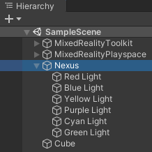
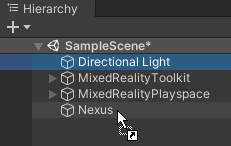
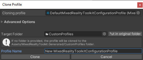
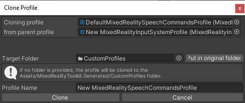
I was creating a canvas with a set of Text Mesh Pro objects on it. Each one had a different part of the overall message, and they needed to be vertically stacked. I thought this would be easy enough. I’d simply attach a Vertical Layout Group to the canvas that the Text Mesh Pro objects were on. I quickly discovered that this didn’t work. The elements didn’t line up correctly. Then I discovered I could add Content Size Fitter on the Text Mesh Pro components. They’d size themselves so the Vertical Layout Group would have the sizing function unchecked, so it would just do positioning. It looked like it worked – sometimes.

Other times, the objects would be stacked on top of one another. I couldn’t literally confirm the behavior, but my suspicion is that I ran into an order of operation problem. When ContentSizeFitter runs first, the sizes are set correctly when Vertical Layout Group comes along, and everything is good. When the order of operations is reversed, well, it’s not so good.

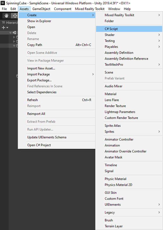
The solution to the problem is a new custom script, which implements both ILayoutElement and ILayoutGroup.

A Preferred Sizer

The objective was to get something that had the behavior of Content Size Fitter where it would expand to the size of the content but at the same time not prevent the Vertical Layout Group from working. Initially, the solution was to derive from ContentSizeFitter and implement the ILayoutElement that it doesn’t implement, but this proved to be challenging. The ContentSizeFitter implements a custom user interface and it didn’t feel worth it to create a brand-new custom user interface for my class. So, I violated a cardinal rule and copied some code from ContentSizeFitter into my new PreferredSizer. I felt justified in this decision, because the real heavy lifting was still being done by the LayoutUtility class that ContentSizeFitter and the various ILayoutGroup implementations still use.

The key implementation pieces were to implement the three width and three height (min, preferred, flexible) to return the value from the RectTransform’s rectangle – if it was present. If it didn’t have a value, it set it to -1.0f – the value that specifies that the value should be ignored. I then took the two methods from ILayoutElement that the consumer is supposed to call before using those values and looped those into the two methods that are called to get the right values from ILayoutSelfController.

The net effect is that, when the parent tries to get the preferred values, it does the internal work to size itself.

Getting Dirty

The last bit that must be addressed is how to inform the rest of the Unity UI system that it’s necessary to rebuild things. That’s done with a bit of a two-step process. There are numerous events that fire and can be captured by the component. These all trigger the need for the PreferredSize to recalculate. The events listed above are all received with methods that simply call SetDirty() to mark the GameObject as needing to be laid out again.

If the GameObject is active (ActiveInHierarchy), SetDirty() calls LayoutRebuilder.MarkLayoutForRebuild() with its RectTransform. LayoutRebuilder is used to signal to the layout system that the component needs to be recalculated, and CanvasUpdatingRegistry can be used to tell if an update is already in progress. Calling MarkLayoutForRebuild() causes your update methods to be called at the appropriate time. It’s the use of these other methods to inform Unity that the user interface needs redrawn that keeps the updates out of the Update() method and improves performance.

LayoutElement

The last bit of the puzzle, which may not be necessary, is to add an additional LayoutElement to the game object and set its Layout Priority higher, so that any values that I want to pin can be set explicitly. The net effect is I have a script that leverages the way that the UI system is intended to operate to size the component. Because of the nature of the ILayoutElement design, I can override that with fixed values.

Object Hierarchy and Scripts in Unity

If you’re a traditional developer, Unity is more than a bit odd. The constructs, for the most part, make sense, but they require that you contort your thinking a bit. In this post, I’m going to walk through object hierarchy, scripting, and reuse.

Game Objects

Everything in Unity is built up from the concept of a game object. A game object is a connection for components. Every game object will have either a Transform or a Rect Transform component associated with it. 3D objects have a Transform – which is a 3D transformation containing the location, rotation, and scale, along X, Y, and Z dimensions. 2D objects have Rect Transform components, which are designed to work with 2D objects even if they exist in a 3D space. Game objects with a Transform don’t fundamentally have a size. Their size is driven by the other components that are attached to the game object.

Game objects can be organized in a hierarchy. This is useful when you want the objects to operate as a unit, as we’ll see as we build out the rotator script and demonstrate its use to create a cluster of directional lights. However, for performance reasons, deep nesting of game objects is discouraged. Largely, this is because some operations are recursive, and a large number of recursive operations can drop the frame rate of the solution unacceptably low. (Below about 60 frames per second.)

Frame of Reference

In the post Creating A Spinning Cube with Unity and MRTK, I created a single object – called Nexus – which had child objects of lights. To Nexus, we attached a rotation script and rotated Nexus. This caused all the lights associated with Nexus to rotate and move. We were able to set the context of the lights local to Nexus, and whatever Nexus did, the light objects would do as well.

This illustrates why we need to be careful with object hierarchy inside of Unity. When we do one operation, we’re impacting seven objects inside the hierarchy. The greater the depth of the hierarchy and the more objects, the more things need to be manipulated – or at least checked – for a single operation.

Scripts and Game Objects

In Unity, scripts are C# code that is associated with a game object. Placing a script in the project does nothing until it’s connected to an instance of a game object. Game objects themselves can be almost anything – including nothing but a container with a Transform component, like the Nexus game object. When we added the script as a component of the game object, we connected the script and told Unity to instantiate the class and connect it to the game object that we added it to.

Including public properties in the script allowed us to set those properties in the editor and ultimately have one script act on multiple objects in different ways. Unity automatically tooled our Camel case names and added spaces before the capital letters to make it more readable. It also provided an editor for the complex Vector3 object. This makes it easy to create scripts that are reusable across objects and for different purposes.

Creating the Spinning Cube Program with Unity and MRTK

In this post, I’m going to walk through the creation of a spinning cube program in Unity. For this demo, we’ll build it with the Mixed Reality Tool Kit (MRTK) and set it up so that you could deploy it to a HoloLens 2. A spinning cube is sort of the 3D equivalent of “Hello World.” So, it’s a good starting point for developing with Unity and using MRTK.

I’m going to use this as an opportunity to explain script reuse and how you can use the same script with parameters with multiple objects. I’m also going to use this as an opportunity to explain basic game object hierarchy and how you can rotate a parent object to cause all the child objects to rotate as well. Finally, we’ll use this project to show off the MRTK orbital component that will allow us to keep objects in the center of view.

To make this project work, we’re going to create one cube object, an empty game object, six directional lights, and one rotator script. We’re going to use the lights to change the appearance of our cube as it spins. The standard material for the cube will reflect the light if we change the colors. By using the orbital component in MRTK, we’ll give the user a way to inspect the object from different angles, even while things are rotating.

Getting the Project Ready

Rather than replicating the steps necessary to create a new project and configure it with MRTK and set it set to deploy to the HoloLens 2, I’m going to refer you to the first 16 steps in the post Building a Unity Project with Speech Recognition using MRTK for a HoloLens 2. The only change we’ll make is that we’ll name the project SpinningCube, since that’s what we’re doing.

Adding the Cube and Lights

[Note: We’ve intentionally continued the numbering throughout the entire post so that we can refer to unique steps in the post.]

Let’s get started by adding our cube and the lights.

  1. Click the GameObject menu and click the Create Empty option.

  2. Right-click on the GameObject in the menu, select the Rename option, then type a new name called Nexus.

  3. Click and hold the Directional Light object and drag it into (under) the Nexus object.

  4. Right-click the Directional Light and click the Rename option in the menu. Enter the name Red Light for the light.
  5. With the Red Light selected, go to Inspector panel, and enter the position of X 0, Y 10, Z 5 and a rotation of X 90, Y 0, Z 0. This points the light to a spot 5 meters ahead of the visible camera.

  6. In the light component, double-click the Color option. In the dialog that appears, set the Red (R) to 255, Green (G) to 0, Blue (B) to 0, and make sure that Alpha (A) is set to 255.

  7. Right-click the Red Light object and select Duplicate from the menu. Repeat this process four more times until you have five lights under your Nexus object.
  8. Using the preceding steps (4-7) and following table, reconfigure the lights you duplicated under Nexus:
     

    Position

    Rotation

    Color

    Name

    X

    Y

    Z

    X

    Y

    Z

    R

    G

    B

    Blue Light 10 0 5 0 -90 0 0 0 255
    Yellow Light -10 0 5 0 90 0 255 255 0
    Purple Light 0 0 10 0 -180 0 255 0 255
    Cyan Light 0 0 0 0 0 0 0 255 255
    Green Light 0 -10 5 -90 0 0 0 255 0
  9. Create the cube by clicking GameObject, 3D Object, Cube from the menu.

You’ll notice that the cube appears to have a different color on each side. If you check the material for the cube, you’ll see that the material is a neutral color. The colors that appear on the cube are coming from the different lights we added to the scene.

Adding the Orbital Component

One way to make it possible to see what we’ve done is to add an Orbital component that comes as a part of MRTK. We can use this to keep an object (or collection of objects) in front of the camera. Let’s add the Orbital component to our cube and to our lights separately. If we weren’t going to rotate the cube separate from the lights later, we could move the cube under our Nexus object, but since we want different rotations, we’re going to keep these two objects separate.

  1. In the Hierarchy, select the object we named Nexus.

  2. In the bottom of the Inspector pane, click the Add Component button. Start typing orbital and select Orbital when it appears.
  3. Notice that Unity added a SolverHandle and set it to Head in addition to the Orbital component. The SolverHandle is necessary so Orbital knows what it’s tracking. In this case, Head is the same as the primary camera.
  4. In the Orbital component, click the Orient Type dropdown and select Unmodified. This will prevent Orbital from trying to orient the object.
  5. Also, in the Orbital component, change the Local offset’s Y value to zero and the Z value to 2– so the resulting offset is X 0, Y 0, and Z of 2.
  6. Select the Cube object in the hierarchy and repeat steps 11-14.

Testing the App

Now we can test our solution. We can press the Play button to see our cube floating in front of us in the game tab. If we move in the play mode, we can see different sides of our cube. You can right-click in the game window and move your mouse to move around in the 3D game space.

That’s a good start, but let’s create a reusable rotation script.

Adding the Rotator Script

We want to setup two different objects to rotate. First, we want to rotate the cube that we added to the scene, but second, we want to rotate the lights in the scene differently. To do that, we’re going to create a rotate script, and in the next section, we’ll attach the script to objects and configure them.

The script will define two public fields – RotationXYZ and RotationRateScale. The first will set the rotation along each axis, and the second will allow us to scale the rotation speed overall without modifying the individual variables. The only other part of this script will in Update() and will use the Transform component’s Rotate method to rotate the object.

Let’s get started.

  1. In the menu, click Assets, Create, and finally C# Script.

  2. Name the script Rotator and press Enter.
  3. Close the MRTK Project Configurator dialog, then double-click your Rotator script to launch Visual Studio.
  4. Inside the top of the class, define the two public variables:
    public Vector3 RotationXYZ = new Vector3(1.0f, 2.0f, 3.0f);
    public float RotationRateScale = 1.0f;
  5. Inside the Update method, add the following code to rotate the object:
    float totalScale = Time.deltaTime * RotationRateScale;
    Vector3 v3 = new Vector3(RotationXYZ.x * totalScale, RotationXYZ.y * totalScale, RotationXYZ.z * totalScale);
    gameObject.transform.Rotate(v3);
  6. Click the Save All button in the ribbon to save your changes to the script.

The script initializes the rotation to a default rotation of X 1, Y 2, Z 3 degrees per second and an overall scale of 1. The update method uses Time.deltaTime – a global property to determine what fraction of a second has occurred since the last call to Update(). This is the way that we can scale the degree of the rotation based on the framerate that’s happening inside of Unity. The code gets the total scaling for the rotation by multiplying our overall rate scale times deltaTime. Then a new Vector3 is created with the rotation needed, and this is applied via the transform component’s rotate method.

Attaching the Rotator Script to the Cube and the Nexus

Our rotator script is fully functional – but it’s not connected to anything. We connect it to our cube and to our Nexus object by selecting the object and dragging the script into a blank spot in the hierarchy.

  1. Start by clearing the MRTK Project configurator by clicking the X in the upper right-hand corner.
  2. Select the Cube object in the hierarchy.
  3. Drag the Rotator script into a gap between components in the inspector pane and release.
  4. Select the Nexus object and repeat step 24.
  5. In the Inspector panel, in the Rotator component, change the Rotation Rate Scale to 10.

By setting the rotation scale to 10 for the lights, you’re causing the lights and the cube to rotate at different rates, and therefore the surfaces of the cube will turn different colors as different lights start acting on them.

Viewing the Final Solution

To view the final solution, simply press the Play button and watch how the Game tab shows your cube spinning – and with the lights spinning at different rates.

You can now go to Nexus and change the rate – or the individual rotation values for each of the X, Y, and Z components to see different spinning effects. You can also navigate around the scene and the cube and lights will follow you. You can use this to look at different parts of the cube in the scene.

If you want to get the completed project, it’s available at https://github.com/rlbogue/UnityPublic/tree/master/SpinningCube

Building a Unity Project with Speech Recognition using MRTK for a HoloLens 2

In this post, I’m going to do a step-by-step walkthrough for building a project that will do speech recognition for a HoloLens 2. Mostly these steps are the same for anytime you want to use MRTK to recognize speech. In the few places where the settings are specific to the HoloLens 2, I’ll call out what’s specific. Let’s get started.

  1. Launch Unity Hub.

  2. Click the New button and select the version of Unity that you want to use for your project. We’re going to use 2019.4.5f1 for this walkthrough.

  3. Enter the project name and folder for your project, then click Create. We’re going to be using SpeechDemo as our project name.

  4. Once Unity has finished loading (which may take a while), go to Assets, Import Package, Custom Package…

  5. Locate the MRTK Foundation Package that you previously downloaded to your local machine and click OK. In this case, we’re using the 2.4.0 build of MRTK.

  6. When the assets list is displayed, click Import.

  7. After the assets are imported, on the MRTK Project Settings Dialog, click Apply.

  8. Close the MRTK Project Settings Dialog, then go to the Mixed Reality Toolkit menu and select the Add to Scene and Configure… option.

  9. In the File menu, go to Build Settings…

  10. Click the Add Open Scenes button to add the current open scene to the build.
  11. Change the build settings to Universal Windows Platform, and, if you’re using the HoloLens 2, set the Target Device to HoloLens and the Architecture to ARM64. For Build and Run on, select Remote Device. Click the Switch Platform button to complete the switch.

  12. After the platform is switched, the MRTK Project Settings dialog reappears. Click Apply to reapply the MRTK settings, then close the dialog.

  13. In the Build Settings dialog, click the Player Settings button in the lower left-hand corner to show the project’s player settings.
  14. Expand the Player Publishing Settings and change the package name to match the name of the project. (This prevents deployments from overwriting other projects and vice versa.)

  15. Scroll down and expand the XR Settings area of the player. Click the plus button and select Windows Mixed Reality. Doing this will allow the project to open in 3D view on a HoloLens instead of in a 2D slate.

  16. After you apply the Windows Mixed Reality settings, the MRTK Project configuration dialog reappears; just close it.
  17. In the Hierarchy, verify that the MixedReality Toolkit object is selected.

  18. In the Inspector, click the Copy & Customize button to create a copy of the profile. This is done because you cannot make changes to the provided profiles. We’ll be making copies of the main profile, the input profile, and the speech profile over the next several steps.

  19. Click Clone to create the new MRTK profile.

  20. In the Inspector tab, go to Input, then click the Clone button.

  21. In the Clone Profile dialog, click Clone.

  22. Expand the Speech section of the input profile and click the Clone button.

  23. In the Clone Profile dialog, click the Clone button.

  24. Click the Add a New Speech Command button. In the new item that appears on the bottom, enter the word hello. This is the word we’re going to use to trigger our script.

  25. Go to the Assets menu, select Create, and C# Script.
  26. If you’ve never configured Unity to use Visual Studio as the editor for scripts, you may want to do that now by going to Edit and then Preferences... (If it’s already configured, you can skip to step 27.)

  27. Go to External Tools and set External Script Editor to Visual Studio – whatever version you have. We’re using Visual Studio 2019 (Enterprise) for this demo. It is functionally the same as the community version for the purposes of this walkthrough.

  28. Double-click the NewBehaviorScript.cs that was created. Visual Studio appears with the file open.

  29. Enter the interface IMixedRealitySpeechHandler, and then right-click the squiggles and select quick actions to have Visual Studio suggest the using statement for Microsoft.MixedReality.Toolkit.Input. Click this entry or press Enter to accept the change.

  30. In the Startup() method, add the line CoreServices.InputSystem?.RegisterHandler<IMixedRealitySpeechHandler>(this); to register this script to receive events. Right-click the squiggles and select quick actions to have Visual Studio suggest the using statement for Microsoft.MixedReality.Toolkit. Click this entry or press Enter to accept the change.

  31. Add a new method to support the interface, OnSpeechKeywordRecognized() as follows:

    Public void OnSpeechKeywordRecognized(SpeechEventData eventData)

    {

    switch(eventData.Command.Keyword.ToLower())

    {

    case “hello”:

    Debug.Log(“Hello World!”);

    break;

    default:

    Debug.Log($”Unknown option {eventData.Command.Keyword}”);

    break;

    }

    }

  32. Remove the Update() method from the file as it is not used. The completed script appears below:

  33. Save the files.
  34. The MRTK Project Configuration Dialog will appear; just close it.
  35. Associate the script to the MixedReality Toolkit object in the game hierarchy by dragging it to between two components in the object in the Inspector window.

  36. Run the application and say “hello.” In the debug window, you’ll see Hello World!

    If you want to get a copy of the final project, it’s available at https://github.com/rlbogue/UnityPublic/tree/master/SpeechDemo

Unity Packages Overwrite One Another On HoloLens and HoloLens 2

By default, Unity packages will overwrite one another as you deploy them through Visual Studio to the HoloLens and Hololens 2. This is due to the package name being defaulted to Template3D for all new projects (created via the 3D Template project.)

To fix the problem, go to Build Settings and press the Project Settings button in the lower-left corner, or go to Edit – Project Settings…

In the project settings dialog, navigate to Player (on the left), expand the Publishing Settings section, then change the value in the package name.

You’ll need to delete the directory that you created the build in (the directory you use when you press the Build button on the Build Settings dialog). Allow Unity to recreate the directory, compile, and deploy via Visual Studio as normal.

Recent Posts

Public Speaking